Because we build OTL amplifiers, people often think that we are making a conventional Futterman design. This is untrue. Our products are designed around a central concept: that symmetrical designs are inherently low distortion, with excellent stability. We build output transformerless circuits that embrace this idea. This paper is designed to shed some light on the technology involved.
Most of the circuitry used in our equipment was designed in the 1940s and 50s, ostensibly for military purposes. We use differential amplifiers, cascode amplifiers and bridge amplifiers for all of our amplifier building blocks. We will discuss the advantages of each, as well as how they were used to create our Balanced Differential Design®.
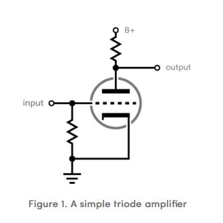
To understand the operation of the more advanced circuitry, it is important to understand the basic circuits. The single-ended triode circuit, shown in Figure 1, has been in use since the 1920s, and is the basic building block of 99% of all tube preamplifiers and most tube amplifiers in use today. It is amazing that so much of what is in use today was designed so long ago.
The triode amplifier in its basic form as shown has a low parts count, good linearity (compared to pentode and transistor circuits) and low cost. It is subject to drift due to aging, has fair power supply noise rejection and relatively low gain. Distortion can be substantially reduced by adding a cathode resistor, but at the expense of gain and increased output impedance. To achieve higher gains, two such stages can be put in tandem by the use of a coupling capacitor. Such an amplifier is known as a triode cascade amplifier.
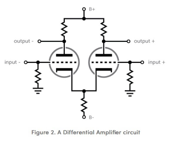
Differential amplifiers are the basic building block of our voltage amplifiers. Differential amplifiers have a number of advantages over conventional single-ended amplifiers. Differential amplifiers are a type of balanced amplifier, although certainly not the only type. A differential amplifier consists of two single stages of gain, connected together by their cathodes (or other emitting devices in the case of semiconductors). This means that a differential amplifier has two inputs and two outputs. Any signal at the input of one side of the amplifier will result in two outputs, equal but 180 degrees out of phase.
On the bench, in the textbook, and in real life, differential amplification provides greater performance, particularly from DC to 100 KHz, the audio region. Reliability in practical terms equals or exceeds that of conventional single-ended circuits, if designed properly.
Advantages
Greater power supply immunity. Differential amplifiers present a constant load to the power supply, resulting in less noise in the power supply. Differential amplifiers also resist input (noise) from the power supply to a much greater degree. Lower noise. Differential amplifiers have roughly 6 dB lower noise than the same circuit executed in a single-ended manner. This can be very important in moving-coil preamp sections. Lower distortion. Differential amplifiers tend to cancel distortions in the output that single-ended amplifiers cannot. Less drift. Drift is reduced by the tight coupling of the two halves of the amplifier. Performance over time is improved. Noise rejection. Common-mode rejection ratio is the measurement of a differential amplifier's ability to not amplify noise that is common to both inputs. It is typically at least 55 dB, and can approach 140 dB in some critically-tuned designs.
Disadvantages
Increased cost. Differential amplification takes more parts to execute. For a given number of stages of gain, differential amplifiers have about 50% more parts. Greater complexity. Although the number of stages of amplification remains the same for single-ended and differential amplifiers, differential amplifiers have more requirements to execute, for example, a negative-voltage power supply.
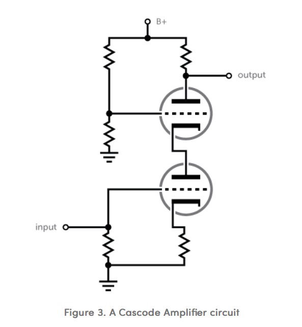
Cascode amplifiers also use two triodes in a single stage of gain. In this case, the plate of the first tube is used to drive the cathode of the second (top) tube, as shown in Figure 3. The top tube is arranged as a constant current source, which has the effect of acting like the circuit of Figure 1 with a very large plate resistor and a very high plate voltage. In this arrangement, the gain and linearity are substantially improved over basic triode amplifiers. The gain can approach the amplification factor of the tube squared, which means that gain is nearly that of a pentode circuit, but with low distortion typical of triode amplifiers.
Advantages
High gain. Lower noise (for the amount of gain developed). Good high frequency bandwidth. This varies with stray capacitance and the internal inter-electrode capacitance of the tubes used. Low parts count (for the amount of resulting gain). This means a simpler circuit design and an overall less expensive device.
Disadvantages
Possibly higher output impedance with certain tubes like the 12AX7.
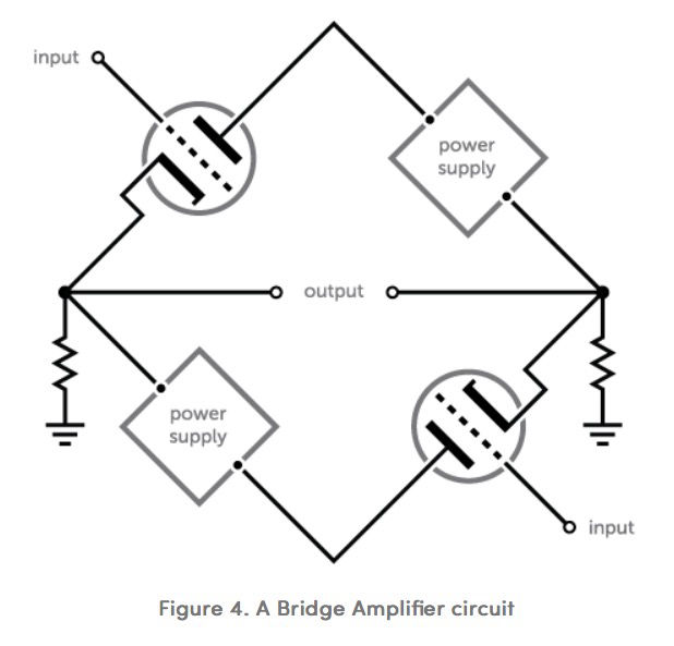
A bridge amplifier is a type of balanced amplifier with unique properties. One of the most important is the ability to couple the output of the amplifier directly to any voltage level. This means that a bridge amplifier can be direct-coupled as a preamplifier or amplifier output at ground potential. A bridge amplifier consists of two single-ended amplifiers connected together as shown in Figure 4. Thus it has two inputs and outputs like a differential amplifier.
Advantages
High stability. This type of amplifier is extremely stable, regardless of input signal or circuit load. Wide bandwidth. Due to the low number of components, bandwidth is limited by stray capacitance. The result is that high power versions of this circuit can have response suitable for RF applications. Symmetrical operation. See differential amplifiers above. Distortion components can cancel in the load circuit. High reliability. Even with catastrophic failure of an output device (be it a tube or a transistor), the lack of delicate parts in the output section prevents damage from occurring to anything except the failed device. Immunity to supply and load variations. The Radiotron Designer's Handbook (RCA, 4th edition), describes bridge output amplifiers: "[...]regulation of plate and filament supplies usually becomes unnecessary. These are normally used only in laboratory instruments." In addition, the reduced output impedance and improved stability allow the amplifier to operate normally with extreme loads, although performance may be compromised.
Disadvantages
Increased cost. This is mostly due to the second disadvantage: Greater complexity. Requires two independent, but equal, floating power supplies.
By creative combination of the above circuitry, we have created a tube circuit not used in tube amplifiers before: the differential cascode. This type of circuit has all the advantages of cascode and differential amplifiers, resulting in an amplifier that has fewer parts for the amount of gain available than is possible using conventional triode circuits, while at the same time having lower distortion and noise. This, plus the use of bridge amplifiers, makes possible our power amplifier and preamplifier circuitry which is fully differential and balanced from input to output. We call this Balanced Differential Design®.
The advantage of this technique is that distortion is canceled at each stage in the circuit, meaning that the succeeding stage will not have to amplify that distortion. This results in much lower distortion and natural sound, while at the same time allowing for high gain and low noise. Our preamplifier has the greatest phonograph input sensitivity of any tube preamp made (good to .07 mv), and yet there are only three gain stages in the entire preamplifier. The result is ultimate simplicity, reliability and musicality, which is the hallmark of this type of amplification. In addition, Atma-Sphere music systems, inc. has developed a method of further reducing distortion in the bridge amplifier, while retaining its normal advantages. Thus it is possible to create an amplifier with extremely low distortion and wide bandwidth, even without negative feedback. This allows improved dynamic range, which enhances realism.
The overall effect of this technology is the first "high tech" vacuum-tube line ever conceived and manufactured. Furthermore, a new level of musicality is also achieved, without sacrificing reliability.
References
For the inspired enthusiast of vacuum tube technology, the following texts are extremely informative and well worth the effort to find. Good Luck!
Langford-Smith, F. editor. Radiotron Designer's Handbook, fourth edition. Amalgamated Wireless Valve Co. PTY. LTD. (Australia), reproduced by RCA. 1952.
Tremain, Howard. The Audio Cyclopedia. Howard W. & Co., Inc. 1969.
Valley, Jr., George and Henry Wallman, editors. Vacuum Tube Amplifiers. McGraw-Hill for the MIT Radiation Laboratory. 1948.